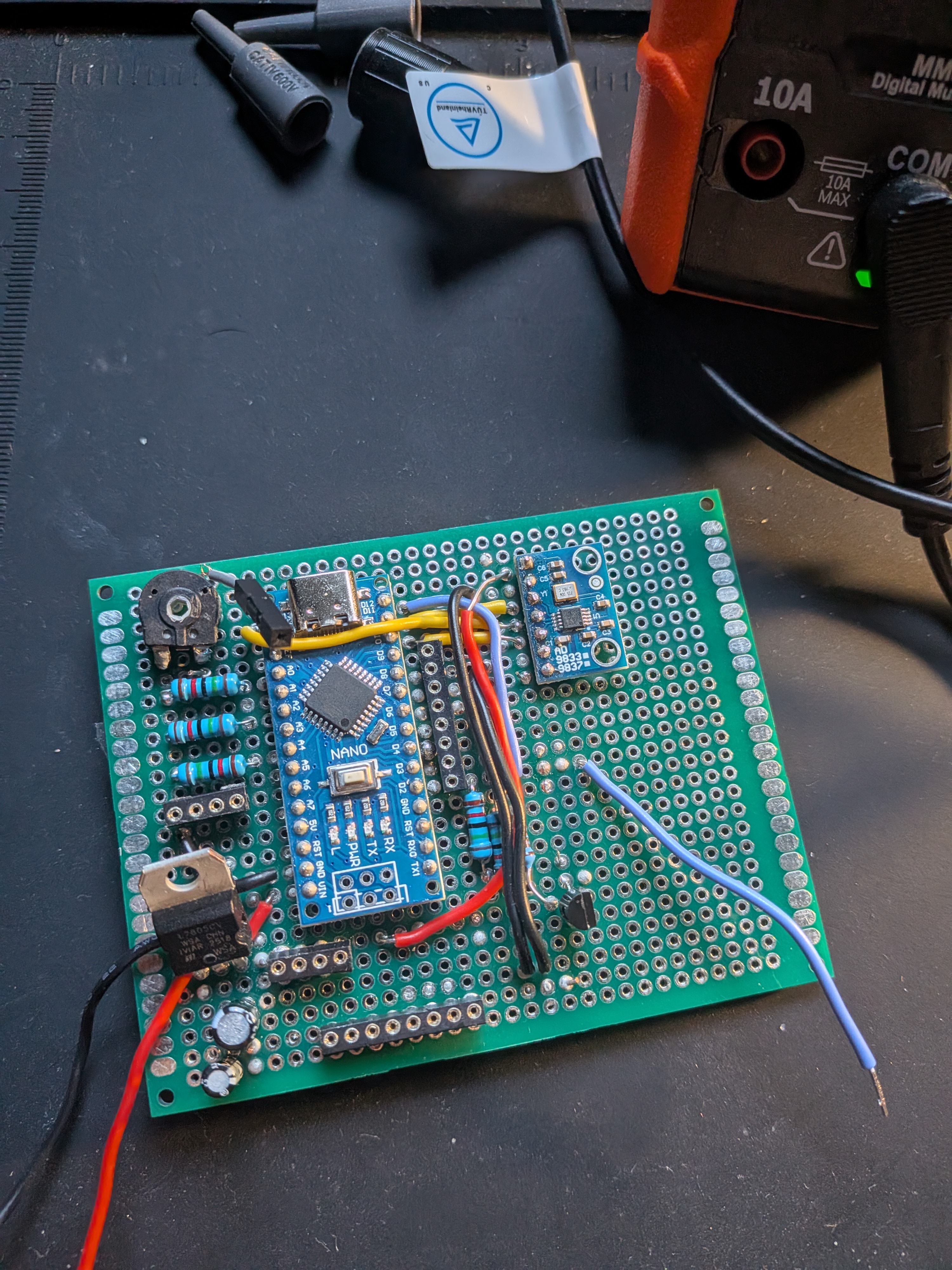
DDS Function Generator
IMSAI Guy, one of my favorite electronics Youtubers, recommended those interested in tinkering with electronics to build their own equipment if their lab is lacking it. I've invested a fair amount into a nice oscilloscope (RIGOL DHO812), but I've been using a spliced 3.5mm audio cable and a pure tone generator on my computer as a makeshift function generator. As you might be able to guess, this has been far from ideal. I decided making a function generator would be a great solution!
Plan
I wanted something fairly compact and simple to use and reliable within the audible range. After some thinking, I came up with these requirements:
- Powered by 12V DC wall wort
- Reliable between 0-100kHz
- 5V peak to peak max output, most things I make require only small signals
- Sine, square, and triangle wave output
- LCD display to show frequency and amplitude
At first, I thought of doing a purely analog function generator for the cool-ness factor of doing something without having to program it.. But I shortly realized that the analog options available were going to be significantly more complicated than it was worth, in my case. After some research I found the AD9833 direct digital synthesis chip, which is low power, easy to program, affordable, and had most of the output capability I was looking for. The only thing lacking was the adjustable output voltage. But this actually made for a great excuse to add some analog components into this project! The AD9833 actually has a much wider frequency range than I need, with a nominal max frequency of 12.5MHz, but signal quality begins to significantly degrade after around 8MHz. Fine by me! More than enough.
A rough start
I decided to start with the digital side of things first since it seemed like it would likely be the most complicated portion of the project. This included the microcontroller and all of the supporting hardware, the AD9833, the screen, mode switches, and rotary encoder. At the time I began this project, I only had Arduino UNO R3s (well, knock-off elegoo UNO R3s). I realized that I did not want the entire dev board in my project, so I decided to use the ATMega328p standalone. So I ordered a 16MHz crystal in a tin-can package for the timer, and got to work. It was all going well at first, and worked when tested on a breadboard. Then came time to solder it up, which LOOKED really pretty.. Still quite proud of the outcome. However, after testing everything, it didn't work, and I couldn't for the life of me figure out why. I decided to desolder the AD9833 in order to try a new design, but in doing so, broke it D: While only about 10 dollars, it was definitely the most expensive part of this project.
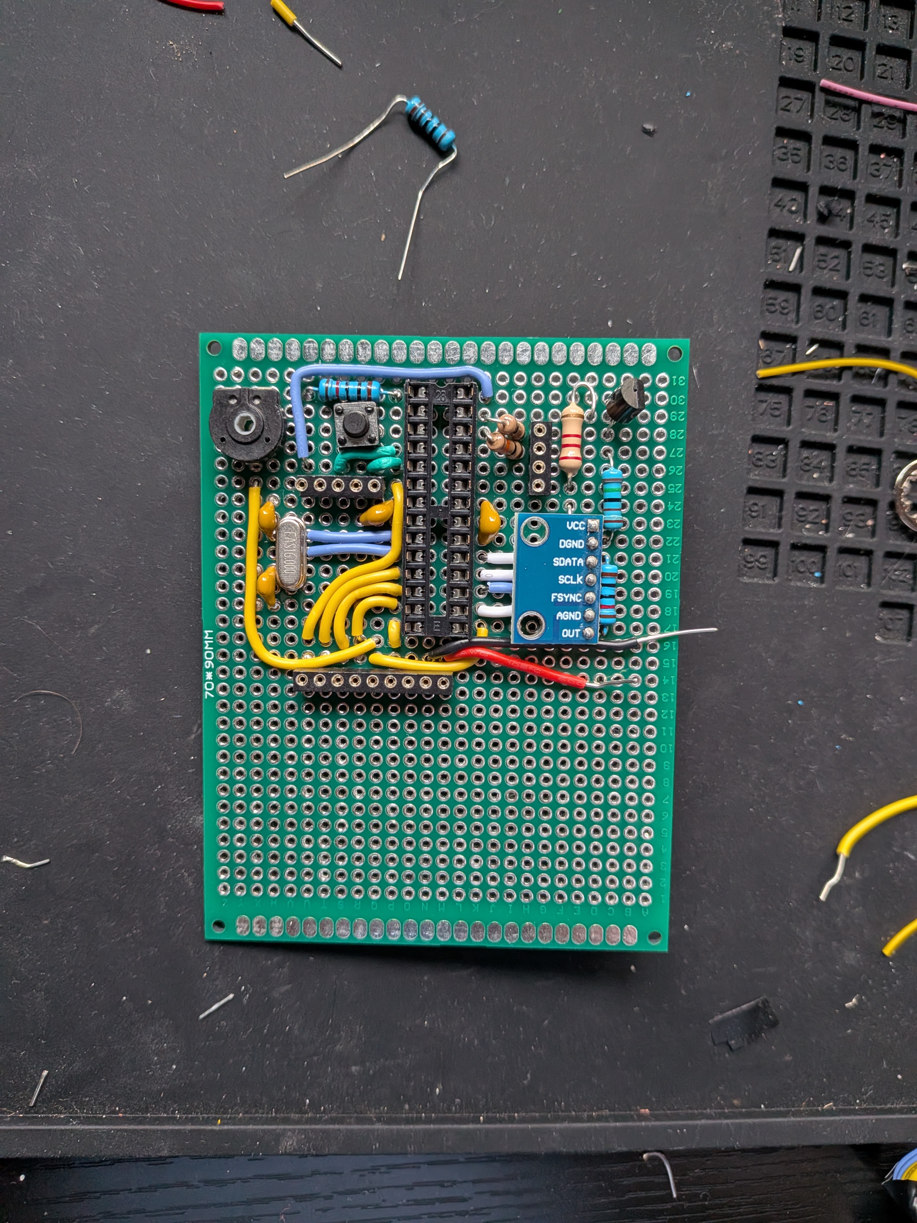
Peripheral upgrades
After the hiccoughs (hiccups?) with the digital section I decided to take a break and focus on the peripherals. For the peripherals, I needed to modify the LCD screen, encoder, and mode switch so that I could mount them off-board, and not use the built-in pins. At first I only had solid-core wire, and I did not have any proper connectors, so I did my best... But to be honest this was pretty janky! I used chopped up DIP sockets as the pins, where one side would be used for the pins, and the other side was used for the sockets.. This was servicable but I was definitley NOT a good long-term solution. Solid core wire also is NOT ideal for off board components because of how stiff it is.
Anywho, here is "version 1" of the peripherals
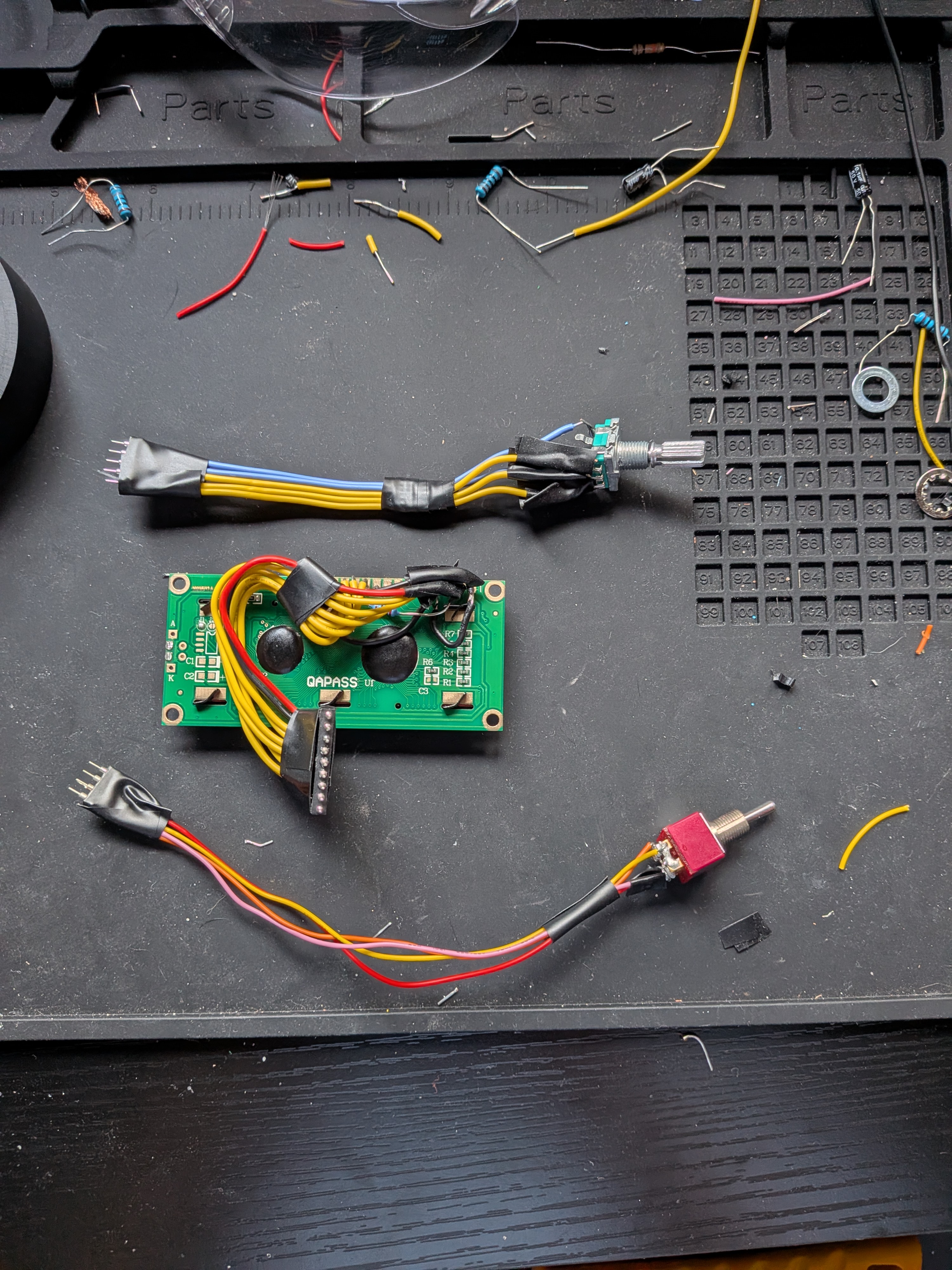
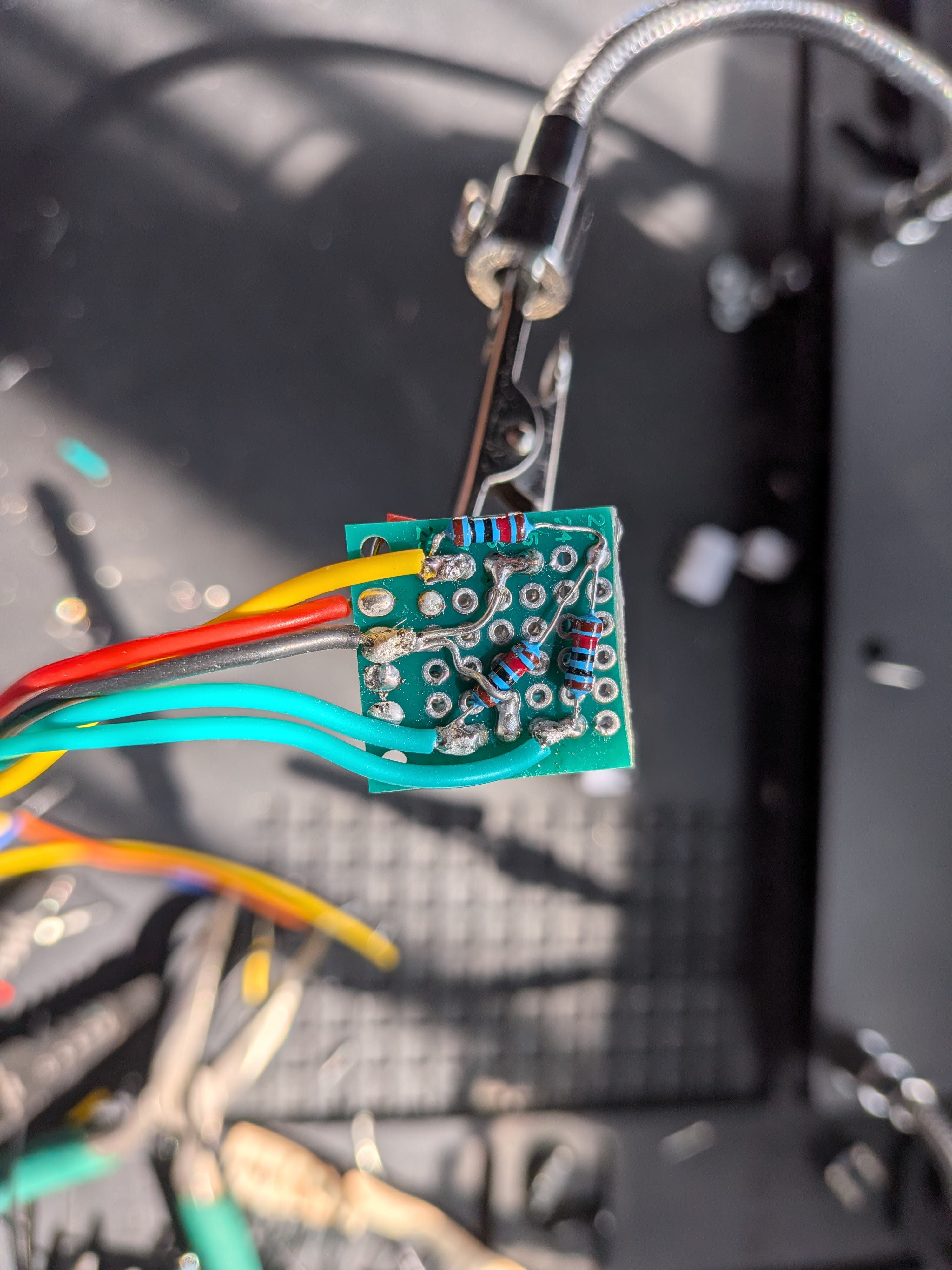
Throughout the process of testing the board, the solid core wire became extremely frustrating to work with. Also, the rotary encoder didn't have solder lugs for the pins as it was meant to be mounted on board. So, after breaking a few encoders from the pins bending, I finally decided to make a breakout board that had all of the pullup resistors and also to securely mount the encoder. I just used some perf-board and cut it to size. Quite proud of how it looked! It also meant I didn't need any pullup resistors on the main board, which saved some space.
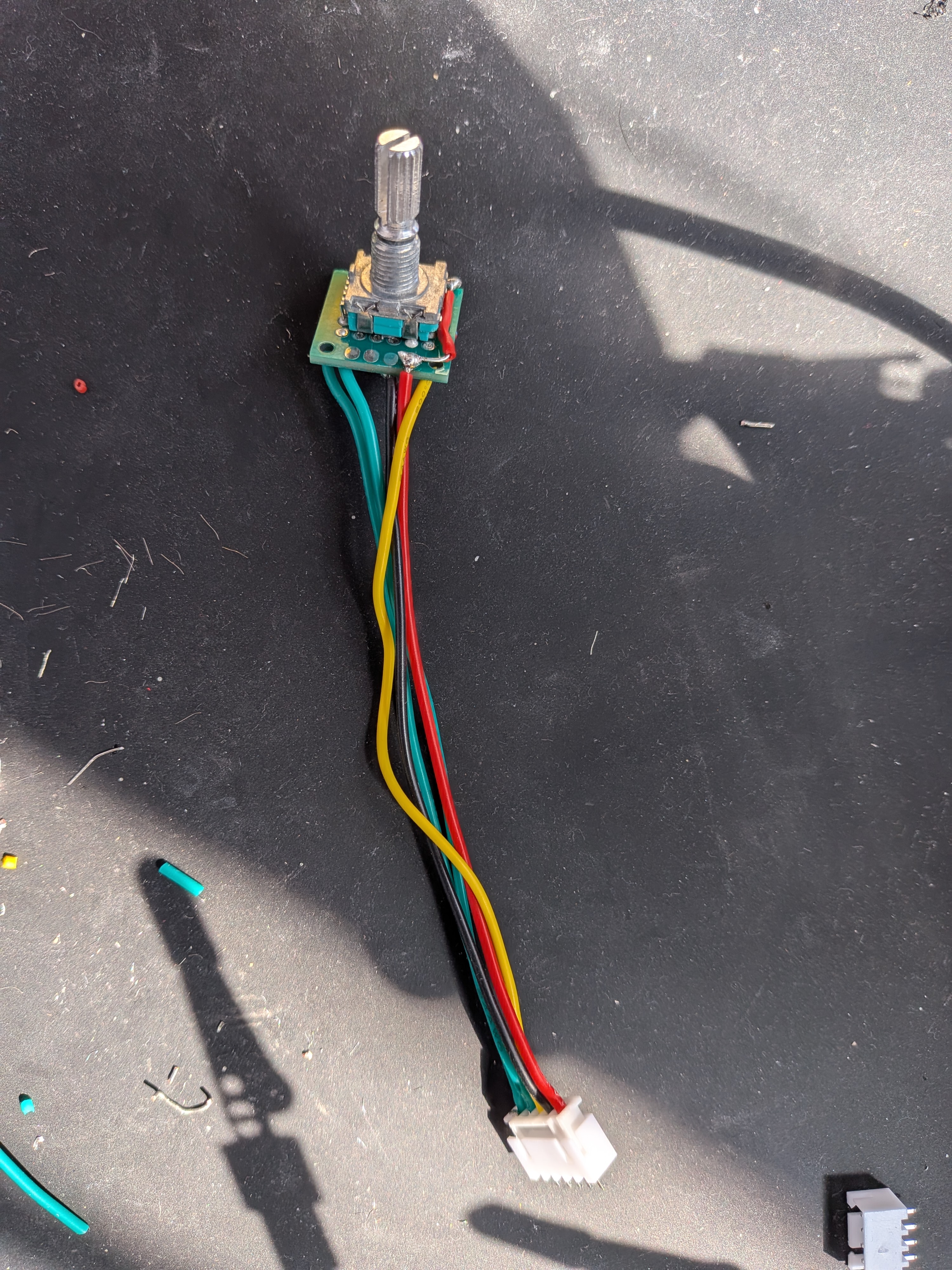
I also went ahead and bought some flexible stranded wire and proper JST connectors! This combined with some more well-developed soldering skills and a bit more patience made for some MAJOR improvements on the LCD. So far this was the most satisfying result of the whole project.
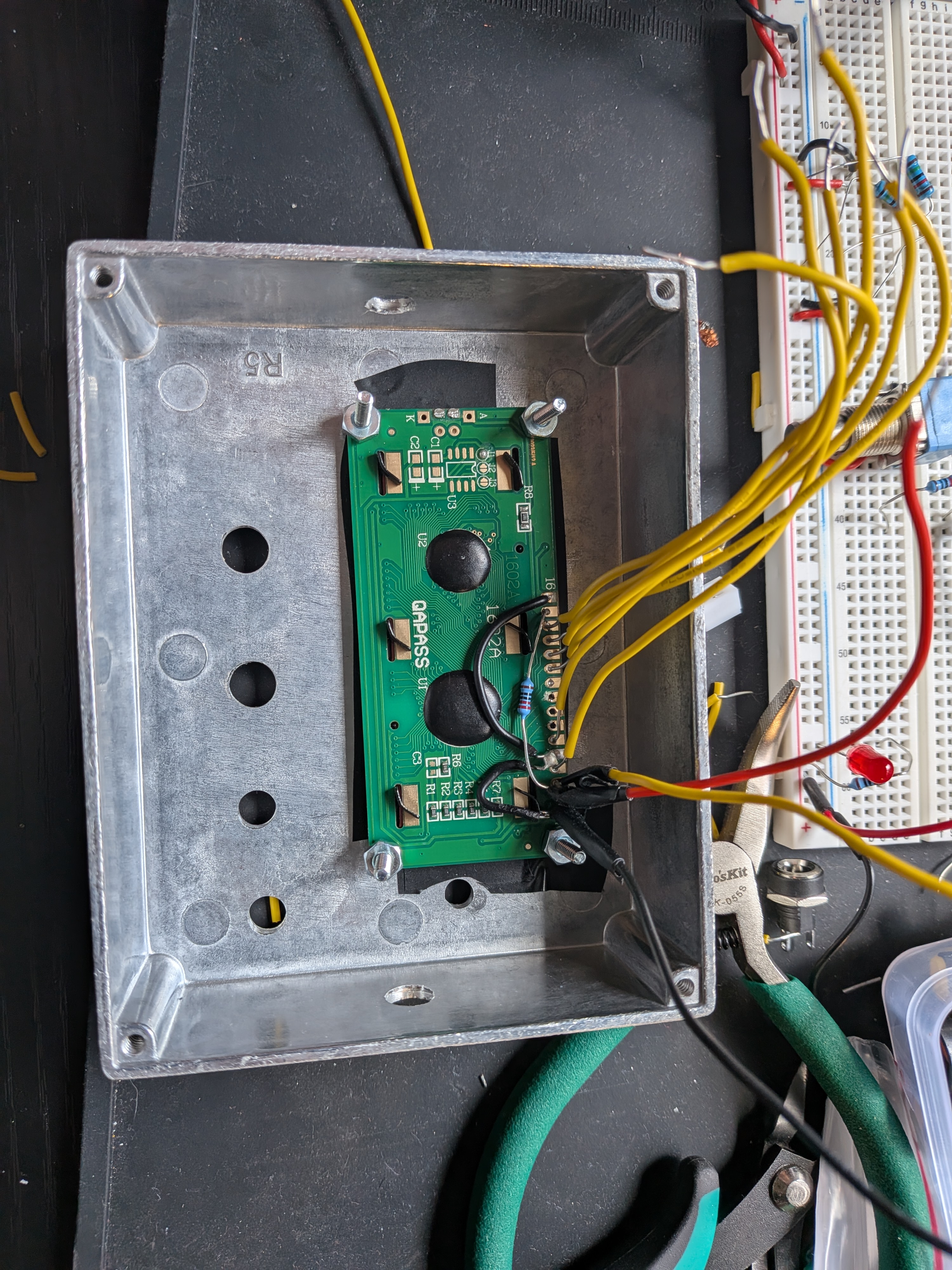
Out with the old and in with the new!
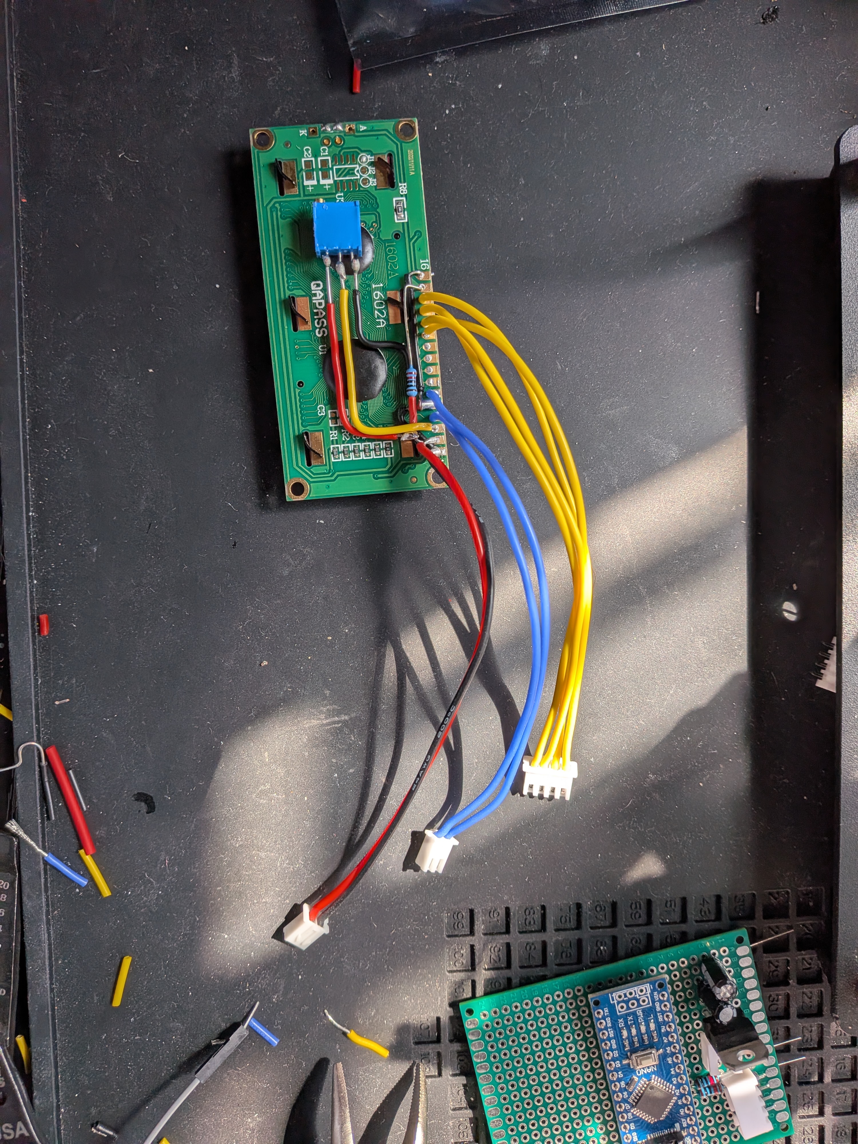
I also had the clever idea (not to pat myself on the back too much) of putting a little trimmer pot directly on the LCD for the contrast to further save on main board space.
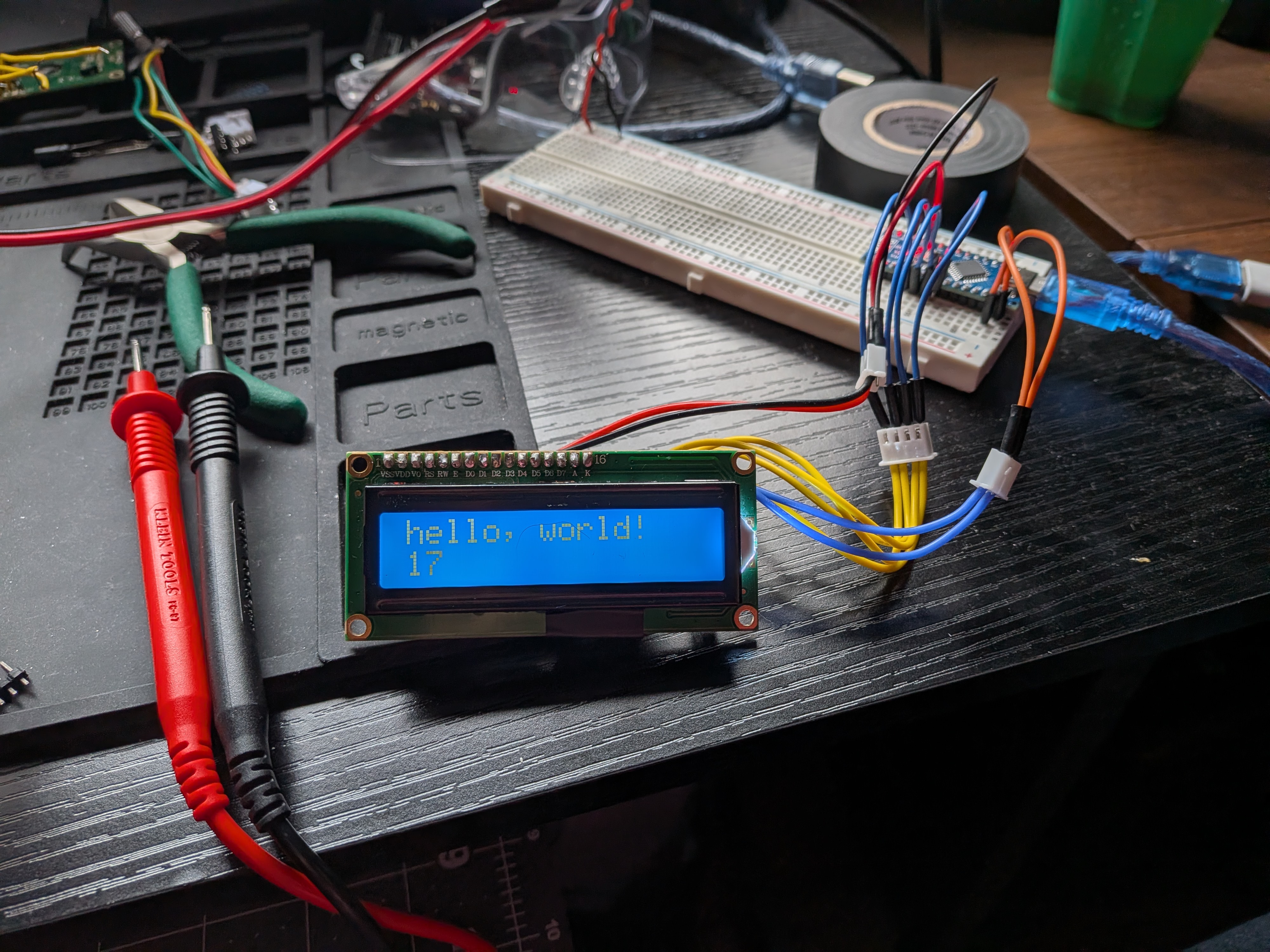
Hello Arduino Nano
After frustrations with the standalone ATMega328p, I realized that buying a 5 pack of Arduino Nano for 10 dollars was well worth my time.